| /CaseStudy /Download /Feedback /ModuleDescription /ProgramSchedule /Resources |
Formal Software Specification (UML Modelling)
Contents
- day 1 intro, user requirements analysis (14 March 2005)
- day 2 specifying objects and relations (15 March 2005, morning only)
- day 3: specifying dynamic behavior (18 March 2005)
- day 4: case study specification (21 March 2005)
- day 5: case study implementation (22 March 2005)
- day 6: evaluation (29 March 2005, till 16.00)
- Emotion-based Instant Messaging
- Competency Area(s) Developed
- Competency Area(s) Developed and Competency Levels Achieved
- Feedback on Deliverables
- Feedback on Assignment Approach and Attitude
- Advice
- Slides and Handouts
- Software packages to start with
- Modelling and programming tools
- Binaries
- Source code and documents
- Requirements
- Installation
- Screenshots
A product with sensors, actuators and network connections can offer an interesting, useful, or playful behaviour to its users and to the other products, systems and services to which it is connected. The ID Master takes responsibility for the creation of this behaviour. If the product isn’t stand-alone, neither is the designer. Whenever product behaviour is realised through computer software and protocols, the designer takes advantage of being an excellent communicator in these matters. In present-day software engineering, the Universal Modelling Language UML has become widely accepted. It contains “activity diagrams”, “use case diagrams”, “class diagrams”, “state charts” and “message sequence charts”. The knowledge and skills that students get by participating in this module will help them to express the structure and behaviour of the software components in their design in a way that is understood by third parties. Starting from elementary programming skills, which are a prerequisite, the student will develop an understanding and appreciation of what it means to master complexity. The scope is widened from small programs to real complex software systems. Although developing and maintaining such systems usually involves computer scientists as well, the ID Master will be well equipped to use UML and thus specify system structure and desired behaviour.
Panos Markopoulos, Yuechen Qian, Jun Hu and Loe Feijs will work together to provide background information, explain UML and create a learning experience in which reading UML, writing UML, and creating software come together.
Contents
- day 1 intro, user requirements analysis (14 March 2005)
- day 2 specifying objects and relations (15 March 2005, morning only)
- day 3: specifying dynamic behavior (18 March 2005)
- day 4: case study specification (21 March 2005)
- day 5: case study implementation (22 March 2005)
- day 6: evaluation (29 March 2005, till 16.00)
Schedule for ID Master Module M3, Software modelling and specification
1. day 1 intro, user requirements analysis (14 March 2005)
- Welcome
user requirements specification: activity diagrams, use case diagrams Panos
(continues in afternoon)
2. day 2 specifying objects and relations (15 March 2005, morning only)
- Workshop
lecture + exercises on class diagrams Yuechen
3. day 3: specifying dynamic behavior (18 March 2005)
- Workshops (morning)
lecture + exercises on state charts Yuechen
lecture + exercises on sequence charts Yuechen
4. day 4: case study specification (21 March 2005)
- Case study (morning)
specifying the system using activity diagrams, use case diagrams (expert: Panos)
specifying the system using class diagrams (expert: Jun)
specifying the system using state charts (expert: Jun)
specifying the system using sequence charts (expert: Jun)
5. day 5: case study implementation (22 March 2005)
- Case study (all day)
introduction to the case study's Java platform (Jun)
6. day 6: evaluation (29 March 2005, till 16.00)
- Case study (morning)
7. Emotion-based Instant Messaging
All students work in a team to develop an extenstion to an existing instant messaging system that,
- analyzes the messages and filters the emoticons in the message;
- calculates current emotional state of the buddies based on the collected emoticons,.
- keeps track of the emotional state history of the buddies.
The existing instant messaging system will be provided as a blackbox with the following interfaces:
- sending messages.
- notification of the messages received.
- changing the user's status.
- notification of the status change of the buddies.
- file transfer.
The team should not work on:
- network communication,
- session management,
- user profiles,
- conversation management etc.
- Task Code Mater Module
- M3
- Module Name
- Software modeling and specification
- Assignor
- Feijs, Markopoulos, Hu, Qian
- Task Completed
- Yes
8. Competency Area(s) Developed
Integrating Technologies (Software modeling and specification)
9. Competency Area(s) Developed and Competency Levels Achieved
- You have learned different notations in UML and applied those techniques in designing an add-on for an instant messaging system.
- You have obtained basic understanding of object orientation.
Feedback on Competencies Developed and Levels Achieved
- You showed us you are capable of using UML to a certain extend, especially the use case diagram and the class diagram in the analysis phase and the early design phase in a software development project. What seemed difficult was deciding the scope of a use case. As the problem you worked on opened up the box (you were always aware of the system structure into client, server and add-on), it was difficult for you to distance yourselves and write use cases for user tasks. This would be easier if you try to apply use cases in a design project, where abstraction level and scope follow directly from a consideration of user tasks and without reference to systems structure. In all very good progress for the little time they had.
- The state machine diagram and the sequence diagram you presented lacked consistency, and a better understanding of how these diagrams should work was expected. However it was your first attempt to speak a new language, we did not expect you to be fluent.
- There was a gap between the design you presented using the UML diagrams and the implantation in Java. We understood that this was due to the limited time and you had to break the serial design-then-implementation to a parallel one.
10. Feedback on Deliverables
- The final presentation shows that you have achieved the basic goal of this module: understanding what a formal specification language can do and why it is needed.
- The emotion add-on for the instant messaging package worked, although it appeared to be buggy during the final presentation.
- It was very good that you presented your add-on together with the UML class diagrams. It showed that you had developed an object-oriented way of doing things – and that is exactly where the UML is designed for.
11. Feedback on Assignment Approach and Attitude
- You showed interests and attention to the lectures and actively participated in discussions.
- You liked to get hand-on experiences by working on given examples during lectures. Good.
- You have been very attentive, hard working and fun to work with. You got into the spirit of writing use cases and representing them with use case diagrams and activity diagrams.
12. Advice
- You need to practice UML more in other projects and modules whenever you need to express your idea to the users and the engineers. Do not invent a new language where there is already a common one with rich expressions. More specifically,
- In requirement analysis, more attention should be paid on understanding of use cases. To do so, writing down textual use case description is a must. Using activity diagrams to describe dynamic behaviors is also needed (in the final presentation no activity diagram was demonstrated by students). Furthermore, try to be precise when using elements in diagrams.
- In static domain modeling, you should be aware of design steps and design decisions. First classify words (nouns and verbs) in user requirements and define initial domain model and refine them thereafter. Try to follow the steps described in the handouts. Also, you should be conscious about your decision-makings and justify each design decision.
- In dynamic behavior modeling, you should be aware of design steps and design decision as well. First, derive sequence diagrams from use case descriptions. Then, work out collaboration diagrams. Next, build and refine state diagrams. For details, please consult the handouts related to this topic.
- You can consider the UML as a communication tool for you to communicate with the user and software engineers. Your UML diagrams need not to be perfect and accurate – that’s a job for software designers, however, they do need to be communicative and understandable.
13. Slides and Handouts
14. Software packages to start with
15. Modelling and programming tools
UML 2.0 stencils from Pavel Hruby
16. Binaries
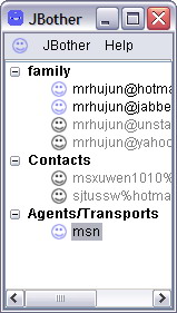
TIM3.jar - the blackbox. A Jabber client based on JBother 0.8.5
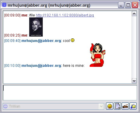
FileTransfer.jar - a plugin for TIM3 for exchanging files/photos.
EmoticonCollector.jar - a plugin for TIM3 to collect emoticons from the conversations.
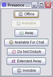
PresenceWatcher.jar - a plugin for TIM3 to monitor/change the status of the user and the buddies.
please notice that these plugins does not work with the original JBother, use TIM3 instead.
17. Source code and documents
18. Requirements
Java 2 JREE 1.4 or above.
19. Installation
19.1. TIM3
Copy TIM3.jar to anywhere you like. Double click on the icon to start the program.
19.2. plugins
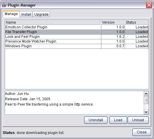
Copy the plugin to <home>/.jbother/plugins. On Linux, <home> is your home directory. On Windhows, <home> is C:\Documents and Settings\<your windows login user name>. You can download these plugins in the plugin manager because these plugins are not part of the standard JBother.
In order to serve the files from your local computer when transferring files, port 8080 will be open for connection. Any other software occupying this port or any firewall security hiding this port will fail the FileTransfer plugin to work properly.
20. Screenshots
- TIM3 in action
- Plugins are loaded
- File Transfer plugin in action
- Emoticon Collector plugin in action
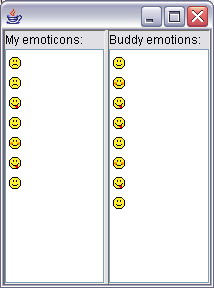
- Presence Watcher Plugin in action
